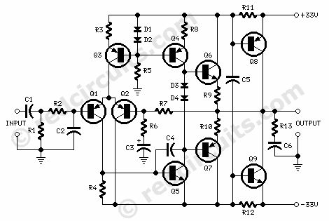
Amplifier circuit diagram:
Amplifier parts:
R1______________18K  1/4W Resistor
R2_______________3K9 1/4W Resistor
R3,R6____________1K  1/4W Resistors
R4_______________2K2 1/4W Resistor
R5______________15K  1/4W Resistor
R7______________22K  1/4W Resistor
R8_____________330R  1/4W Resistor
R9,R10__________10R  1/4W Resistors
R11,R12_________47R  1/4W Resistors
R13_____________10R    1W Resistor


C1_______________1µF  63V Polyester Capacitor
C2_____________470pF  63V Polystyrene or Ceramic Capacitor
C3______________47µF  25V Electrolytic Capacitor
C4______________15pF  63V Polystyrene or Ceramic Capacitor
C5_____________220nF 100V Polyester Capacitor
C6_____________100nF  63V Polyester Capacitor

D1,D2,D3,D4___1N4148  75V 150mA Diodes

Q1,Q2________BC560C   45V 100mA Low noise High gain PNP Transistors
Q3,Q4________BC556    65V 100mA PNP Transistors
Q5___________BC546    65V 100mA NPN Transistor
Q6___________BD139    80V 1.5A NPN Transistor
Q7___________BD140    80V 1.5A PNP Transistor
Q8__________MJ2955    60V 15A PNP Transistor
Q9__________2N3055    60V 15A NPN Transistor
Preamplifier circuit diagram:

Preamplifier parts:
P1______________10K  Linear Potentiometer
P2,P3,P4________47K  Linear Potentiometers
P5______________10K  Log Potentiometer

R1,R2___________33K  1/4W Resistors
R3_____________220K  1/4W Resistor
R4_____________390R  1/4W Resistor
R5,R14___________3K9 1/4W Resistors
R6,R15___________8K2 1/4W Resistors
R7,R16__________12K  1/4W Resistors
R8,R11,R17,R20_560R  1/4W Resistors
R9,R18___________5K6 1/4W Resistors
R10,R19________100R  1/4W Resistors
R12______________3K3 1/4W Resistor
R13_____________18K  1/4W Resistor

C1,C12_________220nF  63V Polyester Capacitors
C2,C13_________100pF  63V Ceramic Capacitors
C3,C14__________10pF  63V Ceramic Capacitors
C4,C15__________47µF  25V Electrolytic Capacitors
C5,C16_________100µF  25V Electrolytic Capacitors
C6,C7___________10µF  25V Electrolytic Capacitors
C8,C11___________4n7  63V Polyester Capacitors
C9______________10nF  63V Polyester Capacitor
C10_____________47nF  63V Polyester Capacitor

Q1___________BC560C   45V 100mA Low noise High gain PNP Transistor
Q2,Q3,Q5,Q6__BC546    65V 100mA NPN Transistors
Q4___________BC557    45V 100mA PNP Transistor

J1,J2__________6.3mm Mono Jack sockets
Power supply circuit diagram:

Power supply parts:
R1_______________3K3  1/2W Resistor

C1,C2_________4700µF  50V Electrolytic Capacitors
C3,C4__________100nF  63V Polyester Capacitors
C5,C6___________47µF  50V Electrolytic Capacitors

D1_____________200V 8A Diode bridge
D2_____________5mm. Red LED

IC2___________78L24  24V 100mA Positive voltage regulator IC
IC3___________79L24  24V 100mA Negative voltage regulator IC

F1,F2__________3.15A Fuses with sockets

T1_____________230V or 115V Primary, 25+25V Secondary 60 to 100VA Mains transformer

PL1____________Male Mains plug

SW1____________SPST Mains switch
Comments:
The power amplifier stage of this design adopts the still new but already successful 45 Watt Class B Amplifier circuitry appeared on the Audio page of this site one year ago. Please follow the link to read more about this circuit.
Simplicity and ease of construction of this amplifier, combined with the complete absence of manual settings make it ideal for Guitar or Bass amplifier. Enjoy!
The preamplifier features two almost identical three-transistor gain-blocks based on a complementary two-stage circuit with dynamic active load of the output transistor. A circuit topology early used in Revox tape recorders and audio preamplifiers with single rail supplies in the 18 - 24Vdc range.
In this preamp the gain blocks are powered by split supplies of ±24V with two advantages: a high output voltage of about 15V RMS allowing a very wide overload margin and the facility to easily derive the preamp power supply from the power amplifier main supply.
A three-band stacked-type tone control is implemented in the second stage but, unlike the more common passive controls, active controls are used here, allowing better signal to noise ratio and overload margin with no gain loss.
Power supply circuitry is straightforward: a generously rated power transformer with center tapped secondary winding is followed by a diode bridge and two big smoothing electrolytic capacitors. Two small positive and negative voltage regulator ICs provide the ±24V @ 9mA dc supply required by the preamp.
Notes:
- 2N3055 and MJ2955 transistors were listed for Q8 and Q9 in the Amplifier parts as the preferred types, but many different output transistors can be used satisfactorily: TIP3055/TIP2955, TIP35/TIP36, MJ802/MJ4502, MJ15003/MJ15004 amongst others.
- Discrete op-amp output transistors Q6 and Q7 do not require any heatsink as their cases remain at ambient temperature. Power transistors Q8 and Q9 should be mounted on a black, finned heatsink as usual.
Power Amplifier Technical data:
- Output power (1KHz sinewave):
- 45 Watt RMS into 8 Ohms - 69W RMS into 4 Ohms
- Sensitivity:
- 0.81V RMS input for 45W output
- Frequency response @ 1W RMS:
- 15Hz to 23KHz -0.2dB
- Total harmonic distortion @ 1KHz:
- 1W 0.008% 20W 0.008% 45W 0.016%
- Total harmonic distortion @10KHz:
- 1W 0.01% 20W 0.015% 45W 0.025%
- Unconditionally stable on capacitive loads
Preamplifier Technical data:
- Maximum output voltage (1KHz sinewave):
- 14.8V RMS
- Sensitivity:
- 127mV RMS input for 14.8V RMS output
- 8.5mV RMS input for 1V RMS output
- Total harmonic distortion @ 1KHz:
- 1V RMS output <0.001% 5V RMS output <0.05%
- Total harmonic distortion @10KHz:
- 1V RMS output <0.001% 5V RMS output <0.035%