Circuit diagram:
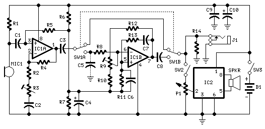
Parts:
P1______________10K  Log. Potentiometer

R1,R10__________10K  1/4W Resistors
R2_______________1K  1/4W Resistor
R3______________50K  1/2W Trimmer Cermet or Carbon
R4,R6,R7,R14___100K  1/4W Resistors
R5______________47K  1/4W Resistor
R8______________68K  1/4W Resistor
R9_______________2K2 1/2W Trimmer Cermet or Carbon
R11_____________33K  1/4W Resistor
R12_____________18K  1/4W Resistor
R13_____________15K  1/4W Resistor


C1,C2,C3,C8,C9_100nF  63V Polyester Capacitors
C4______________10µF  25V Electrolytic Capacitor
C5_____________220nF  63V Polyester Capacitor (Optional, see Notes)
C6_______________4n7  63V Polyester Capacitor
C7______________10nF  63V Polyester Capacitor
C10____________220µF  25V Electrolytic Capacitor

IC1___________LM358   Low Power Dual Op-amp
IC2_________TDA7052   Audio power amplifier IC

MIC1__________Miniature electret microphone

SPKR______________8 Ohm Small Loudspeaker

SW1____________DPDT Toggle or Slide Switch
SW2,SW3________SPST Toggle or Slide Switches

J1____________6.3mm or 3mm Mono Jack socket

B1_______________9V  PP3 Battery (See Notes)

Clip for PP3 Battery
Comments:
Although this kind of voice effect can be obtained by means of some audio computer programs, a few correspondents required a stand-alone device, featuring microphone input and line or loudspeaker outputs.
This design fulfills these requirements by means of a variable gain microphone preamplifier built around IC1A, a variable steep Wien-bridge pass-band filter centered at about 1KHz provided by IC1B and an audio amplifier chip (IC2) driving the loudspeaker.
Notes:
- The pass-band filter can be bypassed by means of SW1A and B: in this case, a non-manipulated microphone signal will be directly available at the line or loudspeaker outputs after some amplification through IC1A.
- R3 sets the gain of the microphone preamp. Besides setting the microphone gain, this control can be of some utility in adding some amount of distortion to the signal, thus allowing a more realistic imitation of a telephone call voice.
- R9 is the steep control of the pass-band filter. It should be used with care, in order to avoid excessive ringing when filter steepness is approaching maximum value.
- P1 is the volume control and SW2 will switch off amplifier and loudspeaker if desired.
- C5 is optional: it will produce a further band reduction. Some people think the resulting effect is more realistic if this capacitor is added.
- If the use of an external, moving-coil microphone is required, R1 must be omitted, thus fitting a suitable input jack.
- This circuit was intended to be powered by a 9V PP3 battery, but any dc power supply in the 6 - 12V range can be used successfully.