Circuit diagram:
Parts:
P1______________47K  Log. Potentiometer
                     (twin concentric-spindle dual gang for stereo)

R1,R2,R4_______100K  1/4W Resistors
R3,R14_________560R  1/4W Resistors
R5_______________1K  1/4W Resistor
R6,R7,R10_______10K  1/4W Resistors
R8,R9___________22K  1/4W Resistors
R11_____________68K  1/4W Resistor
R12______________1K5 1/4W Resistor
R13_____________12K  1/4W Resistor

C1_______________1µF  63V Polyester Capacitor
C2,C3__________100pF  63V Polystyrene or Ceramic Capacitors
C4______________47nF  63V Polyester Capacitor
C5______________22nF  63V Polyester Capacitor
C6_____________220pF  63V Polystyrene or Ceramic Capacitor
C7,C10_________100nF  63V Polyester Capacitors
C8,C11___________4µ7  25V Electrolytic Capacitors
C9,C12________2200µF  25V Electrolytic Capacitors

IC1___________TL072   Dual BIFET Op-Amp
IC2___________78L15   15V 100mA Positive Regulator IC
IC3___________79L15   15V 100mA Negative Regulator IC

D1,D2________1N4002  200V 1A Diodes

SW1____________DPDT  Toggle Switch
SW2____________2 poles 3 ways Rotary Switch

J1,J2,J3,J5____RCA audio input sockets
J4_____________Mini DC Power Socket
Comments:
This is the first article of a five-part series describing a complete audio preamplifier formed by five Mini-Modules, namely: Control Center, Switching Center, Phono Preamplifier, Tone Control and Headphone Amplifier. A suitable Power Amplifier module is already available here: 45 Watt Class B Amplifier.
The arrangement of these modules is similar to a late-1980's commercial production, the Thorens Restek Mini-Modules. Obviously, all the circuits of this Modular Preamplifier are original designs and have no relationship with the Thorens Modules.
The modular arrangement allows the amateur to choose only the modules more suited to his requirements in order to build a chain one to five modules long.
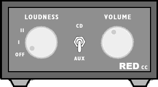
For the minimalist, the Control Center module described in this page will be most probably the only useful module, allowing the choice of two input sources, e.g. a CD player and an Aux input (Tuner or iPod etc.).
The purist can also omit the Loudness control available there: the 2 poles 3 ways Rotary Switch used for this control (SW2) can be converted into a three-input selector switch. Therefore, the two-input selector SW1 at the center of the front panel, can be substituted by a 3mm stereo mini-jack socket, allowing, for example, the quick and easy plugging of an iPod.
Each module, excepting the Switching Center that is a passive circuit, incorporates its own separate power supply rectifiers and regulators and requires only an external 15 - 18V ac (50mA minimum) Power Supply Adaptor.
In a chain formed by several modules, the use of a series of Power Supply Adaptors may be considered excessive. In such cases, the dual ±15V dc stabilized supply can be carried from a main module to the others by means of a three-wire cable and suitable connectors. Or the ac output of a single Power Supply Adaptor can be routed to several modules by using two Mini DC Power Sockets in each module wired in parallel, allowing to use a two-wire cable interconnection.
Each electronic board can be fitted in a standard enclosure: Hammond extruded aluminum cases are well suited to host the boards of this preamp. In particular, the cases sized 16 x 10.3 x 5.3 cm or 22 x 10.3 x 5.3 cm are the more appropriate and can be stacked with advantage.
Control Center circuit description:
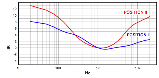
This circuit features two high-level inputs switched by SW1, followed by the unity-gain high input impedance buffer IC1A. The output of this buffer drives the passive network Loudness circuit. Its control switch SW2A allows the choice of two different frequency compensation curves (see graph below) to be used when the sound programme is reproduced at low levels. Curve I should be used with low to mid reproduction levels, in practice when the volume control knob is set around the second quarter of its travel. Curve II is best suited to very low levels, i.e. when the volume control knob is set around the first quarter. To obtain a perfectly flat frequency response, the Loudness control must be set in the OFF position.
The following Op-Amp (IC1B) provides all the gain required by the preamplifier, featuring 166mV RMS input sensitivity at 1.5V RMS output with very low distortion. Therefore it is capable of driving low input sensitivity power amplifiers.
The dual rail power supply necessary for this circuit is drawn from the single 15 - 18V ac voltage provided by a suitable external Power Supply Adaptor. D1 and D2 rectify respectively the positive and the negative half wave in order to obtain a dual opposite polarity rail voltage referred to ground. IC2 and IC3 provide a well regulated ±15V dc supply to the Op-Amps.
Notes:
- The circuit diagram shows the Left channel only and the power supply.
- Some parts are in common to both channels and must not be doubled. These parts are: P1 (if a twin concentric-spindle dual gang potentiometer is used), IC2, IC3, C7, C8, C9, C10, C11, C12, D1, D2, SW1, SW2 and J4.
- This module requires an external 15 - 18V ac (50mA minimum) Power Supply Adaptor.
Technical data:
- Input sensitivity:
- 166mV RMS for 1.5V RMS output
- Maximum output voltage:
- 9.5V RMS into 10K load
- Frequency response:
- flat from 20Hz to 23KHz
- Total harmonic distortion @ 1KHz and 10KHz:
- less than 0.002% at all levels up to 9.5V RMS (0.0017% typical)
Loudness Frequency Response:
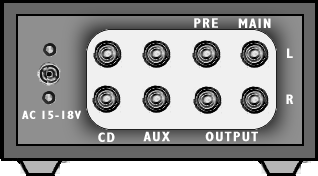
A possible arrangement of the front and rear panels of this Module