Circuit diagram:

Parts:
P1______________47K Log. Potentiometer
(twin concentric-spindle dual gang for stereo)
R1_______________4K7 1/4W Resistor
R2______________12K 1/4W Resistor
R3,R4___________33R 1/4W Resistors
R5,R6____________4R7 1/4W Resistors
C1_______________1µF 63V Polyester Capacitor
C2,C5__________100nF 63V Polyester Capacitors
C3,C6___________22µF 25V Electrolytic Capacitors
C4,C7_________2200µF 25V Electrolytic Capacitors
IC1__________NE5532 Low noise Dual Op-amp
IC2___________78L09 9V 100mA Positive Regulator IC
IC3___________79L09 9V 100mA Negative Regulator IC
D1,D2________1N4002 200V 1A Diodes
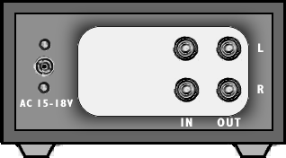
J1,J2__________RCA audio input sockets
J3,J4__________6mm. or 3mm. Stereo Jack sockets
J5_____________Mini DC Power Socket
Comments:
Those wanting private listening to their music programme should add this Headphone Amplifier to the Modular Preamplifier chain.
The circuit was kept as simple as possible compatibly with a High Quality performance. This goal was achieved by using two NE5532 Op-Amps in a circuit where IC1B is the "master" amplifier wired in the common non-inverting configuration already used in the Control Center Line amplifier. IC1A is the "slave" amplifier and is configured as a unity-gain buffer: parallel amplifiers increase output current capability of the circuit.
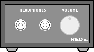
Two Headphone outputs are provided by J3 and J4.
The ac gain of the amplifier was kept deliberately low because this module is intended to be connected after the Control Center module, which provides the gain sufficient to drive the power amplifier.
If you intend to use this Headphone Amplifier as a stand-alone device, a higher ac gain could be necessary in order to cope with a CD player or Tuner output. This is accomplished by lowering the value of R1 to 1K5. In this way an ac gain of 9 is obtained, more than sufficient for the purpose.
Contrary to the two 15V positive and negative regulator ICs used in other modules of this preamp, two 9V devices were employed instead. This because the NE5532 automatically limits its output voltage into very low loads as 32 Ohm in such a way that the output amplitude of the amplified signal remains the same, either the circuit is powered at ±9V or ±15V.
The choice of a ±9V supply allows less power dissipation and better performance of the amplifier close to the clipping point.
The input socket of this amplifier must be connected to the Main Out socket of the Control Center Module. As this output is usually reserved to drive the power amplifier, a second socket (J2) wired in parallel to J1 is provided for this purpose.
As with the other modules of this series, each electronic board can be fitted into a standard enclosure: Hammond extruded aluminum cases are well suited to host the boards of this preamp. In particular, the cases sized 16 x 10.3 x 5.3 cm or 22 x 10.3 x 5.3 cm have a very good look when stacked. See below an example of the possible arrangement of the front and rear panels of this module.
Notes:
- The circuit diagram shows the Left channel only and the power supply.
- Some parts are in common to both channels and must not be doubled. These parts are: P1 (if a twin concentric-spindle dual gang potentiometer is used), IC2, IC3, C2, C3, C4, C5, C6, C7, D1, D2, J3, J4 and J5.
- This module requires an external 15 - 18V ac (100mA minimum) Power Supply Adaptor.
Technical data:
- Output power (1KHz sinewave):
- 32 Ohm: 140mW RMS
- Sensitivity:
- 275mV input for 1V RMS output into 32 Ohm load (31mW)
- 584mV input for 2.12V RMS output into 32 Ohm load (140mW)
- Frequency response @ 2V RMS:
- Flat from 15Hz to 23KHz
- Total harmonic distortion into 32 Ohm load @ 1KHz:
- 1V RMS and 2V RMS 0.0012%
- Total harmonic distortion into 32 Ohm load @ 10KHz:
- 1V RMS and 2V RMS 0.0008%
A possible arrangement of the front and rear panels of this Module