Circuit diagram:
Parts:
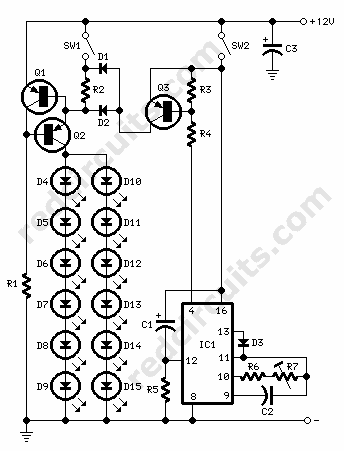
R1,R5___________10K  1/4W Resistors
R2______________33R  1/4W Resistor (See Notes)
R3,R4____________1K8 1/4W Resistors
R6_____________220K  1/4W Resistor
R7_____________500K  1/2W Trimmer, Cermet or Carbon

C1_______________1µF  25V Electrolytic Capacitor
C2______________10nF  63V Polyester Capacitor
C3______________47µF  25V Electrolytic Capacitor

D1,D2_________1N5819  40V 1A Schottky-barrier Diodes or BAT46
D3____________1N4148  75V 150mA Diode

D4--D15_________LEDs  High brightness, high efficiency red types (See Notes)

IC1_____________4060  14 stage ripple counter and oscillator IC

Q1_____________BC557  45V 100mA PNP Transistor
Q2,Q3__________BC327  45V 800mA PNP Transistors

SW1_____________SPST  Tail Light Switch
SW2_____________SPST  Brake Light Switch
Comments:
Designed at the request of several correspondents, the circuit is the merger of two existing designs already available on this site, namely: LED driven tail/brake Light Cluster and Brake Light Signal Module.
In order to obtain a correct operation of both circuits, the original LED driven tail/brake Light Cluster circuit was polarity-reversed: therefore, PNP transistors were used for Q1 and Q2, whereas the Light and Brake switches were connected to the positive rail instead of the negative ground.
Q1 and Q2 form a constant current generator directly supplying the LED Cluster. The constant current level can be set by varying R2 value. When SW1 is on, the cluster will illuminate at medium brightness. When brakes are applied, SW2 will be closed, the cluster will shine at maximum brightness emitting 4 short flashes, followed by a steady on light that remains steady on as long as the brakes are applied.
IC1's internal oscillator generates a square wave whose frequency is divided 64 times by the flip-flops contained in the chip in order to obtain about 1 to 4Hz at pin #4: this is the LED Cluster flashing frequency and can be set to the desired value by means of R7. A positive signal at D3 Cathode stops the oscillator after 5 pulses are counted.
C1 and R5 automatically reset the IC whenever the brakes are applied.
Q3 increases the current flowing through the LED Cluster whenever pin #4 of IC1 goes low.
Notes:
- The cluster can be formed by up to 12 LEDs as shown in the circuit diagram. Common cluster types usually range from 5 to 10 LEDs.
- Using the values shown above, stand-by current with SW1 on was about 20mA.
- Constant output current value can be changed by varying R2.
The formula is: R = 0.6/I (in Amperes). - Use high brightness, high efficiency red LED types of suitable size and change R2 value to suit LED's Absolute Maximum Ratings.
- Any Schottky-barrier type diode can be used in place of 1N5819 or BAT46.