Circuit diagram:
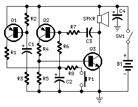
Parts:
R1,R3____________1K  1/4W Resistors
R2,R5___________10K  1/4W Resistors
R4_____________220R  1/4W Resistor
R6_____________220K  1/4W Resistor
R7______________22K  1/4W Resistor
R8_____________100K  1/4W Resistor

C1,C2___________22µF  25V Electrolytic Capacitors
C3______________10nF  63V Polyester or Ceramic Capacitor
C4______________47µF  25V Electrolytic Capacitor

Q1,Q2_________BC557   45V 100mA PNP Transistors
Q3____________BC337   45V 800mA NPN Transistor

SW1___________SPST  Toggle or Slide Main Switch (See Notes)
P1____________SPST  Pushbutton Operating Switch

SPKR__________8 Ohm Loudspeaker

B1____________12V Battery
Comments:
This circuit was requested by several correspondents. Its purpose was to obtain more power than the siren circuit already available on this website since many years (One-IC two-tones Siren) and to avoid the use of ICs.
A complementary transistor pair (Q2 & Q3) is wired as a high efficiency oscillator, directly driving the loudspeaker.
Q1 ensures a full charge of C2 when power is applied to the circuit. Pressing on P1, C2 gradually discharges through R8: the circuit starts oscillating at a low frequency that increases slowly until a high steady tone is reached and kept indefinitely. When P1 is released, the output tone frequency decreases slowly as C2 is charged to the battery positive voltage through R6 and the Base-Emitter junction of Q2. When C2 is fully charged the circuit stops oscillating, reaching a stand-by status.
Notes:
- A good sized loudspeaker will ensure a better and powerful output tone.
- As stand-by current drawing is zero, SW1 can be omitted and B1 wired directly to the circuit.
- Maximum current drawing at full output is about 200mA.