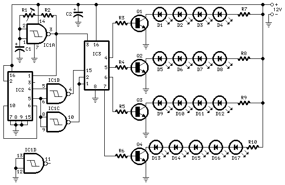
Circuit diagram:

Parts:
R1_____________500K  1/2W Trimmer
R2______________22K  1/4W Resistor
R3,R4,R5,R6______4K7 1/4W Resistors
R7,R8,R9_______470R  1/4W Resistors
R10____________270R  1/4W Resistor

C1_______________4µ7  25V Electrolytic Capacitor
C2_____________220µF  25V Electrolytic Capacitor

D1--D17________LEDs   Any type and color (except blue and white, see Notes)

Q1,Q2,Q3,Q4___BC337   45V 800mA NPN Transistor

IC1____________4093   Quad 2 input Schmitt NAND Gate IC
IC2____________4520   Dual binary up-counter IC
IC3____________4094   8-stage shift-and-store bus register IC
Comments:
A blinking arrow can be a very attractive gadget, suitable for many indication purposes. This circuit provides a bar-mode sequencer driving 17 LEDs arranged in four groups in order to build-up a bright arrow. When the build-up of the arrow is completed, all LEDs stay on for some time, then off for the same time-delay and then the cycle restarts. Sequence speed can be set by R1.
For those wishing to experiment, sequence timings can also be varied by connecting pin #5 of IC1B to pin #5 of IC2 and pins #6, 8 and 9 of IC1 to pin #6 of IC2. Other pin combinations are possibile by shifting the above named pins of IC1 to higher outputs of the counters contained in IC2, i.e. pins #6 and 11, pins #11 and 12 etc.
The resulting effect of the original four groups of 17 LEDs arrangement is shown in the title heading.
Notes:
- Obviously, many different arrangements using more or less LEDs are possibile.
- At 12V supply the maximum number of LEDs per strip is that shown in the circuit diagram, when red LED types are used. Yellow, green and orange types may require a lower value of the limiting resistors or a lesser number of devices per strip.
- Please note that the unused section of IC1 must have the inputs tied to negative ground whereas the output must be left open, as shown at the bottom of the diagram.
