Circuit diagram:
Parts:
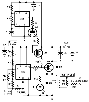
P1_____________100K  Linear Potentiometer
P2,P3___________10K  Linear Potentiometers

R1_____________560K  1/4W Resistor
R2______________68K  1/4W Resistor
R3,R4___________10K  1/4W Resistors
R5______________22K  1/4W Resistor
R6,R7____________4K7 1/4W Resistors
R8_____________330R  1/4W Resistor
R9_______________2K2 1/4W Resistor
R10____________470R  1/4W Resistor
R11_____________47R  1/4W Resistor

C1_______________1µF  63V Polyester Capacitor
C2,C3__________100nF  63V Polyester or Ceramic Capacitors
C4_____________220nF  63V Polyester Capacitor
C5_____________220µF  25V Electrolytic Capacitor

D1______________LED  (Any dimension, shape and color)
D2,D3________1N4148   75V 150mA Diodes

Q1____________BC547   45V 100mA NPN Transistor
Q2,Q3_________BC327   45V 800mA PNP Transistors

IC1,IC2________7555 or TS555CN CMos Timer ICs

T1_____________230V Primary, 12V Secondary 1.2VA Mains transformer (see Notes)

SW1,SW2________SPST  Toggle or Slide Switches

B1_______________3V to 9V Batteries (See Notes)
Comments:
This circuit is a big improvement of the small Muscular Bio-Stimulator design, available on these pages since 2000.
Circuit improvements are due to Bo Braendstrup, from Technical University of Denmark, and feature a very effective and much safer way to adjust output amplitude. Fine adjustments of "Pulse rate" and "Pulse width" were also added, plus a switch allowing to obtain more complex wave forms of the output ac voltage signal (SW1 when closed).
Warning:
The use of this device is forbidden to Pace-Maker bearers and pregnant women.
Do not place the electrodes on cuts, wounds, injuries or varices.
Obviously we can't claim or prove any therapeutic effectiveness for this device.
Notes:
- T1 is a small mains transformer 230 to 12V @ 100 or 150mA. It must be reverse connected, i.e. the 12V secondary winding across Q3 Collector and negative ground, and the 230V primary winding to P3 and output Electrodes.
- The circuit has been thoroughly tested, and it works nicely when supplied in the 3V - 9V range. Running on 3V supply with a 12V 1.2VA transformer it would be no more dangerous than the circuit already published. But please note that using 9V battery supply it can output 120V signals and could be very dangerous.
- Electrodes can be obtained by small metal plates connected to the output of the circuit via usual electric wire and can be taped to the skin. In some cases, moistening them with little water has proven useful.
- Commercial sets have frequently a built-in 30 minutes timer. For this purpose you can use the Timed Beeper the Bedside Lamp Timer or the Jogging Timer circuits available on this Website, adjusting the timing components to suit your needs.