Circuit diagram:
Parts:
P1______________22K  Log Potentiometer
P2______________22K  Linear Potentiometer

R1,R6__________150K  1/4W Resistors
R2_____________220K  1/4W Resistor
R3______________56K  1/4W Resistor
R4_____________470K  1/4W Resistor
R5______________68K  1/4W Resistor
R7______________39K  1/4W Resistor
R8,R13___________3K9 1/4W Resistors
R9______________15K  1/4W Resistor
R10,R11,R15_____10K  1/4W Resistors
R12______________6K8 1/4W Resistor
R14,R17__________5K6 1/4W Resistors
R16____________330R  1/4W Resistor
R18_____________47K  1/4W Resistor
R19______________1M  1/4W Resistor
R20,R21_________22K  1/4W Resistors

C1,C7,C8,C9____330nF  63V Polyester Capacitors
C2______________10µF  25V Electrolytic Capacitor
C3,C10,C11_____100µF  25V Electrolytic Capacitors
C4______________47nF  63V Polyester Capacitor
C5_______________2µ2  25V Electrolytic Capacitor
C6_____________220µF  25V Electrolytic Capacitor

Q1,Q2_________BC557B  45V 100mA PNP Transistors (or 2N3906)

IC1____________TL062  Low current BIFET Dual Op-Amp

J1,J2__________6.3mm. Mono Jack sockets

SW1____________1 pole 3 ways rotary or slider switch
SW2______________SPST Toggle, slider or Pedal Switch
SW3______________SPST Toggle or slider Switch

B1_________________9V PP3 Battery

Clip for PP3 Battery
Comments:
In the old days of tube guitar amps a tremolo circuit, i.e. an amplitude modulator of the input audio signal, was invariably present, even in the cheapest amplifiers. In practice, the signal level was increased and decreased at a rate typically ranging from about 5 to 10 times per second.
This effect is no longer available in most modern guitar amps, but since some players like to use it yet, a stand alone, 9V battery powered tremolo unit primarily intended for electric guitars was designed on request.
Circuit description:
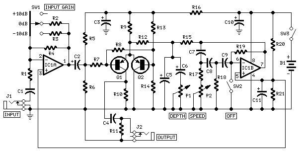
IC1A is wired as a linear input amplifier. The input sensitivity of the circuit can be varied from -10dB to +10dB in three fixed steps by means of SW1, in order to cope with almost any pick-up type and model. The audio signal is then routed to the modulator stage formed by a transistor long-tailed pair (Q1 and Q2) whose tail current is made variable by the output voltage of a sine wave generator. The amplitude modulator circuitry is rather complex if compared to usual tremolo circuits, but it allows superior distortion and overload margin performance. IC1B is wired as a sine wave phase-shift oscillator: its output frequency can be varied in the 5Hz - 10Hz range by means of P2 (Tremolo Speed Control).
P1 is the Tremolo Depth Control: a more or less heavy modulation of the tail current of Q1 and Q2 is obtained by a partial shunting, through the network formed by R12, R15, C5, C6 and P1, of the sine wave generated by IC1B. If a log potentiometer is used for P1, as recommended, a very fine Depth Control will be obtained, ranging from a fixed tone to a gently wavering sound and finally to a more in-deep modulated tremolo.
C4 and R11 form a 160Hz high-pass filter, necessary to reduce the presence of unwanted 5-10Hz frequencies at the output of the circuit.
Notes:
- P1 pins connection: with the shaft of the pot pointing toward you and the three pins pointing down, connect C6 to the leftmost pin and the remaining two pins to negative ground.
- P2 pins connection: with the shaft of the pot pointing toward you and the three pins pointing down, connect R17 to the rightmost pin and the remaining two pins to negative ground.
Technical data:
- Input Gain:
- Three selectable positions: +10dB, 0dB and -10dB
- Maximum Input Voltage:
- 250mV RMS for undistorted output (SW1 set to 0dB)
- 750mV RMS for undistorted output (SW1 set to -10dB)
- 85mV RMS for undistorted output (SW1 set to +10dB)
- Speed:
- Adjustable from 5 to 10Hz
- Total current drawing:
- 1.7mA