Power Amplifier Circuit diagram:

Power Amplifier Parts:
P1______________50K  Log. Potentiometer (or 47K)
                     (twin concentric-spindle dual gang for stereo)

R1_______________1K  1/4W Resistor
R2,R3__________100R  1/4W Resistors
R4______________22K  1/4W Resistor

C1_______________1µF  63V Polyester Capacitor
C2______________47µF  25V Electrolytic Capacitor
C3______________33pF  63V Polystyrene or Ceramic Capacitor
C4_____________220nF  63V Polyester Capacitor
C5,C6__________220µF  25V Electrolytic Capacitors

IC1__________NE5534   Low noise Single Op-amp

Q1____________BD438   45V 4A PNP Transistor
Q2____________BD437   45V 4A NPN Transistor

J1______________RCA audio input socket
Comments:
This amplifier was designed in order to fill the gap in the 3-10 Watts power output range of the audio amplifiers available on RED Free Circuit Designs.
Therefore a simple, very low parts-count amplifier, was designed on the same guidelines of the successful 45 Watt Class B Amplifier, but using the excellent NE5534 IC instead of a discrete component op-amp to drive the output "dumper" transistors.
Due to the maximum operating voltage restrictions of the chip, the output power cannot exceed 7.5 Watts into 8 Ohm loads, but the Total Harmonic Distortion figures are astonishingly low, much lower than comparable audio amplifiers using a single IC audio amp. Also due to the internal current limiting of the NE5534, the output power into 4 Ohm loads will be no more than 8 Watts.
Other interesting features of this amplifier are the absence of any kind of setup and the possibility to be driven directly by the audio source (CD player, Tuner, iPod etc.).
In any case, a simple, optional preamplifier circuit is provided, allowing to cope with very low output audio sources and featuring a single-knob bass and treble Tone Control.
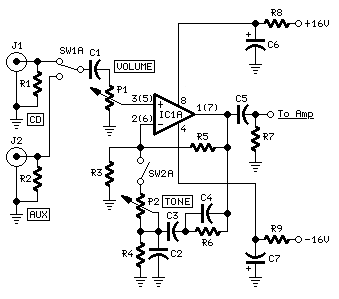
Preamp Circuit diagram:
Preamp Parts:
P1______________50K  Log. Potentiometer (or 47K)
                     (twin concentric-spindle dual gang for stereo)
P2_____________100K  Linear Potentiometer
                     (twin concentric-spindle dual gang for stereo)

R1,R2__________100K  1/4W Resistors
R3______________56K  1/4W Resistor
R4______________15K  1/4W Resistor
R5_____________220K  1/4W Resistor
R6______________22K  1/4W Resistor
R7______________47K  1/4W Resistor
R8,R9__________100R  1/4W Resistors

C1,C5____________1µF  63V Polyester Capacitors
C2______________22nF  63V Polyester Capacitor
C3______________12nF  63V Polyester Capacitor
C4_______________3n3  63V Polyester Capacitor
C6,C7___________47µF  25V Electrolytic Capacitors

IC1___________TL072   Dual BIFET Op-Amp

SW1____________DPDT  Toggle Switch
SW2____________DPST  Toggle Switch (Optional, see Text)

J1,J2__________RCA audio input sockets
Comments:
Though the amplifier can be driven into full power by many audio sources, this simple, optional preamp was devised. It allows to choose from two input sources by means of SW1 and provides a one-knob tone control (P2).
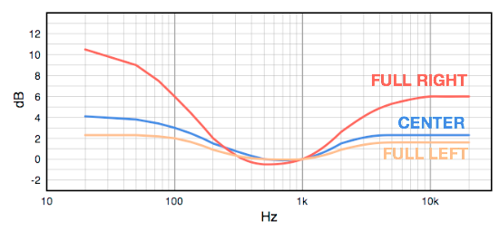
As tone controls are usually employed only to increase bass and treble frequencies, this uncommon control type lifts of a very small amount these frequencies when its knob is rotated fully anticlockwise, gradually increasing them as the knob is rotated clockwise (see curves below). Opening the optional switch SW2, a perfectly flat frequency response will be obtained.
The preamp is connected to the same power supply of the amplifier and its output should be connected to pin 3 of IC1 in the Power Amplifier. Obviously, J1, C1 and P1 of the Power Amp must be omitted (and shifted as part of the preamp).
Tone Control Frequency Response:
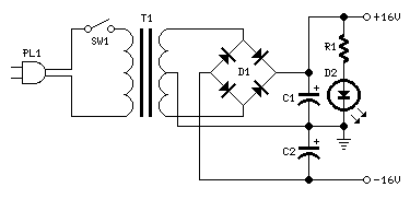
Power Supply Circuit diagram:
Power Supply Parts:
R1_______________1K5 1/4W Resistor

C1,C2_________2200µF  25V Electrolytic Capacitors (or 3300µF 25V, see Text)

D1_____Diode bridge  100 to 400V, 1.5 to 4A
D2______________LED  Any type and color

SW1_____________SPST Mains switch

T1______________230V Primary, 24V Center-tapped or 12 + 12V Secondary,
                     about 30VA or 1.5A, Mains transformer

PL1_____________Male Mains plug with cord
Comments:
The power supply is straightforward. The parts values suggested are suited to power a stereo version of this design. For a mono amplifier a less powerful mains transformer can be used, having a 24V Center-tapped or 12 + 12V secondary winding rated at about 20VA or 0.8-1A.
Either 2200µF or 3300µF filter capacitors will do the job, though the lower value is good for a mono version and the higher is well suited for stereo.
Notes:
- Q1 and Q2 in the Power Amplifier should be mounted on the same finned heatsink, of about 80x40x25mm.
- For the stereo version of this project, IC1, R8, R9, C6 and C7 in the Preamp will be in common to both channels: therefore, only one item each is necessary. IC1 pin numbers in parentheses refer to the second op-amp available into the chip (IC1B).
Technical data:
- Output power:
- 7.5 Watt RMS into 8 Ohm (1KHz sine wave) - 8 Watt RMS into 4 Ohm
- Input sensitivity of the complete Amplifier:
- 65mV RMS for full output
- Power Amplifier Input sensitivity:
- 330mV RMS for full output
- Power Amplifier Frequency response @ 1W RMS:
- flat from 20Hz to 20KHz
- Power Amplifier Total harmonic distortion @ 1KHz:
- 500mW 0.003% 1W 0.0035% 4W 0.002% 7W 0.002%
- Power Amplifier Total harmonic distortion @10KHz:
- 500mW 0.007% 1W 0.0045% 4W 0.0015% 7W 0.006%
- Unconditionally stable on capacitive loads
- Preamp Maximum output voltage:
- 9.5V RMS
- Preamp Frequency response:
- flat from 20Hz to 23KHz
- Preamp Total harmonic distortion @ 1KHz and 10KHz:
- less than 0.002% at all levels up to 9.5V RMS (0.0017% typical)