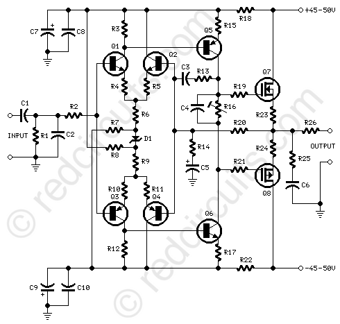
Circuit diagram:
Parts:
R1,R20__________10K   1/4W Resistors
R2_______________1K   1/4W Resistor
R3,R12___________1K5  1/4W Resistors
R4,R5,R10,R11__100R   1/4W Resistors
R6,R9___________18K   1/4W Resistors
R7,R8____________3K3  1/4W Resistors
R13____________150K   1/4W Resistor
R14____________560R   1/4W Resistor
R15,R17_________22R   1/4W Resistors
R16____________500R   1/2W Trimmer Cermet
R18,R22________100R   1/4W Resistors
R19,R21________330R   1/4W Resistors
R23,R24,R26_______R22   5W Resistors (wirewound)
R25_____________10R   2.5W Resistor

C1_______________1µF   63V Polyester Capacitor
C2_____________330pF   63V Polystyrene or ceramic Capacitor
C3______________10pF   63V Polystyrene or ceramic Capacitor
C4_____________220nF   63V Polyester Capacitor
C5_____________220µF   25V Electrolytic Capacitor
C6,C8,C10______100nF   63V Polyester Capacitors
C7,C9__________220µF   63V Electrolytic Capacitors

D1___________BZX79/36  36V 1/2W Zener Diode (See Notes)

Q1,Q2________BC546     65V 100mA NPN Transistors
Q3,Q4________BC556     65V 100mA PNP Transistors
Q5___________MJE350   200V 500mA PNP Transistor
Q6___________MJE340   200V 500mA NPN Transistor
Q7___________2SK1058  160V 7A N-Channel MOS FET Transistor
Q8___________2SJ162   160V 7A P-Channel MOS FET Transistor
Power supply circuit diagram:
Parts:
R1_______________3K9   1W Resistor

C1,C2_________4700µF  63V Electrolytic Capacitors (See Notes)
C3,C4__________100nF  63V Polyester Capacitors

D1_____________400V 8A Diode bridge
D2_____________5mm. Red LED

F1,F2__________4A Fuses with sockets

T1_____________230V or 115V Primary, 35+35V Secondary 160-200VA Mains transformer

PL1____________Male Mains plug

SW1____________SPST Mains switch
Comments:
In an interesting article about "Symmetry in audio amplifier circuitry" published on Electronics & Wireless world, January 1985, pages 31-34, the late and celebrated J.L. Linsley Hood wrote:
"There are difficulties in relying on one's own or on other listeners' ears for quality assessments in audio circuitry. However, it is possible to form opinions on the nature of circuit structures which lead to favourable audience responses, and of these the most readily defined is that of symmetry in the circuit architecture.
Of course, one must accept that true symmetry, as between NPN and PNP devices, or between those of N-channel or P-channel construction, is not really practicable, simply because of mobility of electrons and holes is so dissimilar. Nevertheless, at low frequencies, some measure of mirror-image symmetry is feasible, and this seems sometimes to be preferred by listeners when two otherwise similar circuit structures are compared.
In contemplating this observation, it is tempting to rationalize this preference as a consequence of the sensitivity of the ear to any slew-rate limiting effects, since it can be argued that in a truly symmetrical structure the inevitable stray load capacitances will be driven in both polarity directions and will, in consequence, have betters slewing characteristics than a single-ended driver system".
Therefore, a symmetrical amplifier as simple as possible was designed and its circuit diagram is shown above.
A relative inconvenience of symmetrical audio circuit configurations is that of maintaining a constant mean current through the amplifying device, a problem which does not arise when the load is itself a constant current source, and some external feedback network is employed to stabilize the d.c. working point, as in the more conventional amplifier topology always adopted in our earlier designs.
Therefore, to ensure maximum stability, in addition to a single Zener diode (D1) used to stabilize the input stage and consequently also the driver stage currents, the use of V-MosFets in the output stage becomes mandatory.
For this purpose, the well renowned Hitachi 2SK1058 and 2SJ162 pair was employed with excellent results.
Notes:
- Please do not attempt to replace the prescribed Hitachi MosFet power transistors with different devices.
- Please note that the pin layout of the Hitachi MosFets is different from most MosFet types on the market.
- A 36V Zener diode (D1) could be not easy to locate. This drawback can be overcome by wiring in series a 24V and a 12V or two 18V Zener diodes.
- Quiescent current can be measured by means of an Avo-meter wired in series to the positive supply rail, with no input signal.
- Set Trimmer R17 to its minimum resistance.
- Power-on the amplifier and adjust R17 to read a current drawing of about 100mA.
- Wait about 15 minutes, watch if the current is varying and readjust if necessary.
- The value suggested for C1 and C2 in the Power Supply Parts List is the minimum required for a mono amplifier. For optimum performance and in stereo configurations, this value should be increased to at least 10000µF.
- A correct grounding is very important to eliminate hum and ground loops. Connect to the same point the ground sides of R1, C2 and C5 and the ground input wire. Connect C7 to C10 to output ground. Then connect separately the input and output ground to the power supply ground.
Technical data:
- Output power:
- 75 Watt RMS into 8 Ohm (1KHz sinewave) - 110W RMS into 4 Ohm
- Sensitivity:
- 1.2V RMS input for 76.5W output
- Frequency response:
- Flat from 40Hz to 20KHz
- -0.5dB @ 30Hz
- -1.2dB @ 20Hz
- Total harmonic distortion @ 1KHz:
- 1W 0.0025% 10W 0.002% 20W 0.004% 50W 0.009% 70W 0.017%
- Total harmonic distortion @10KHz:
- 1W 0.005% 10W 0.013% 20W 0.013% 50W 0.05% 70W 0.1%
- Unconditionally stable on capacitive loads