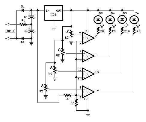
Circuit diagram:
Parts:
R1______________10R    1W Resistor
R2,R3,R4,R5_____50K  1/2W Trimmers Cermet or Carbon
R6_____________100K  1/4W Resistor
R7______________27K  1/4W Resistor
R8,R9,R10,R11__330R  1/4W Resistors

C1,C2___________47µF  50V Electrolytic Capacitors

D1,D2________1N4002  100V 1A Diodes
D3-D6__________LEDs  (Any color and size)

IC1___________78L05    5V 100mA Regulator IC
IC2___________LM339  Quad Voltage Comparator IC
Comments:
If you want a simple but precise audio power indicator to be connected to the output of any amplifier whose power output lies in the 0.5W-50W range, you should consider to build this circuit, featuring four adjustable LED indicators that can be set to any output power comprised in the above cited range.
Though ICs are employed, a battery or power supply is not necessary for this circuit, because the supply voltage is derived from the audio signal coming from the amplifier.
The ac signal voltage present at the input of the circuit is easily doubled and rectified by two diodes (D1 & D2) and two capacitors (C1 & C2), then feeds the regulator IC whose output delivers a fixed voltage (5V) to the rest of the circuit.
The voltage present at IC1 input is also used to feed the inverting inputs of four comparators through the voltage divider formed by R6 & R7.
By means of four trimmers (R2 to R5) each comparator can be set to trigger at any voltage needed and activates its respective LED.
Setting up:
The simplest way to connect this circuit to the amplifier output is to use a twisted pair cable terminated with two insulated crocodile clips.
Setup is best accomplished with an oscilloscope or an audio millivoltmeter like the one described in these pages: Precision Audio Millivoltmeter.
A 1KHz sine wave generator with variable output is also required (see two suitable circuits in this website also: 1KHz Sinewave Generator and Spot-frequency Sine wave Generator).
Connect the generator to the amplifier input and the Audio Power Indicator to the output of the amplifier, in parallel with the oscilloscope probe or the audio millivoltmeter input. When using high power outputs disconnect the loudspeakers to avoid Tweeters damage and connect in their place an 8 Ohm 20-30 Watt wirewound resistor.
Remember that VRMS output is equal to output Peak-to-Peak Voltage divided by 2.828. RMS power output in Watts is equal to VRMS2 divided by speaker impedance (usually 8 or 4 Ohm). Example: set the output of the 1KHz sinewave generator to read 14V on the audio millivoltmeter (24.5W @ 8 Ohm). Set R2 until D3 illuminates, and be sure that D3 turns-off when diminishing a little the generator's output.
Do the same with other comparators, setting each comparator to trigger when the desired output power is reached.